Product page, before and after
A product-family page for the same filters: hero copy, a spec table with conditions, an eight-question technical FAQ and the inquiry-form questions.
Coming soon
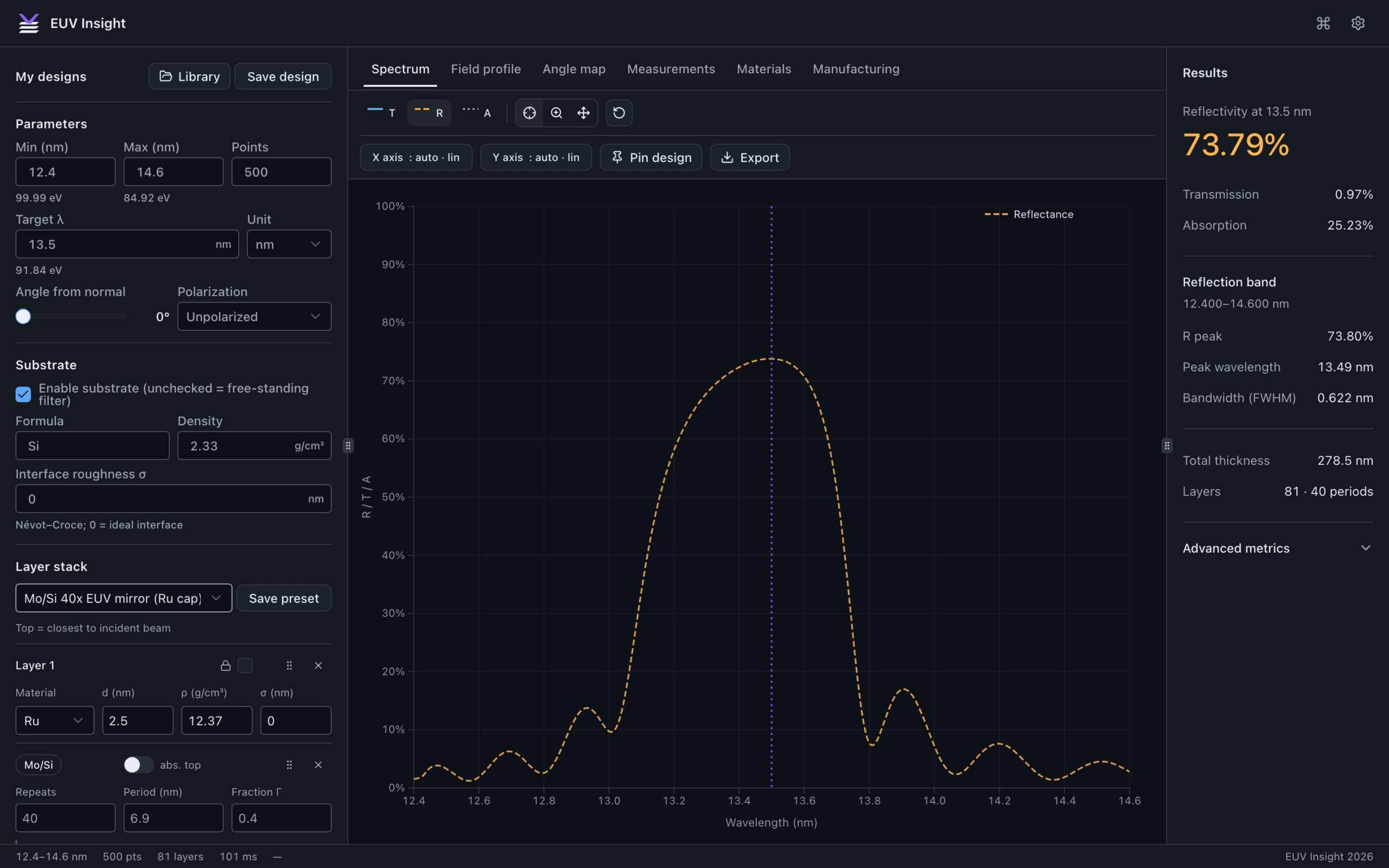
EUV Insight is a thin-film design app I built for optics engineers. The document samples below include public references and calculation files.
A CAD view of a photodiode readout board, showing the photodiode connections, adjustment controls, and power and signal connectors.
Explore readout electronics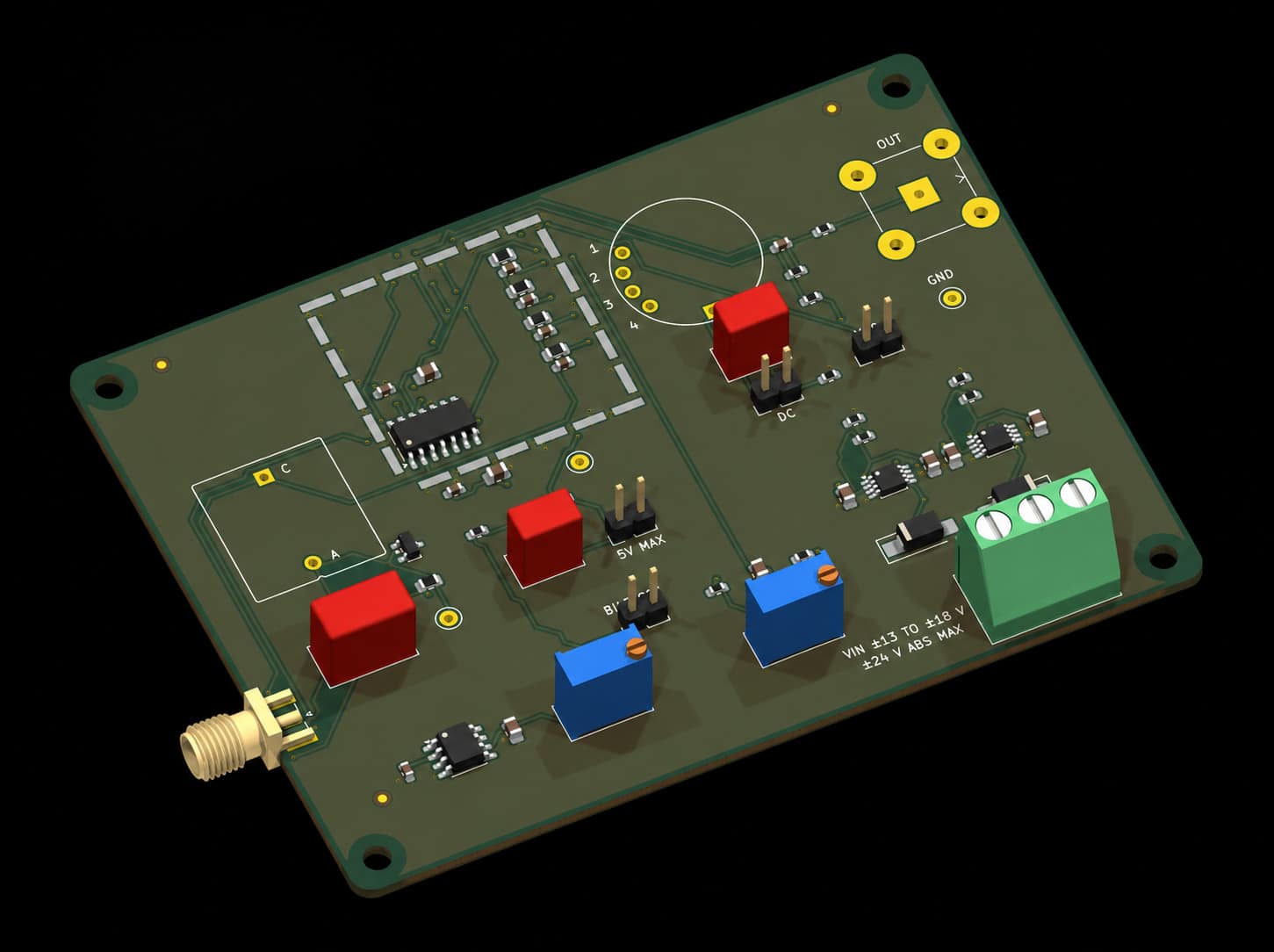
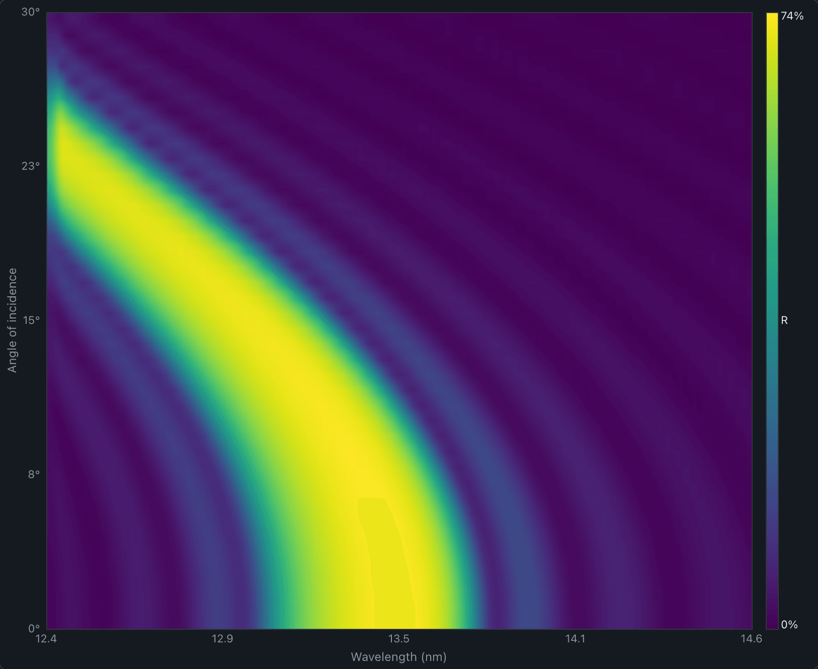
I built EUV Insight to calculate the optical response of EUV thin films and multilayer stacks. Change the materials and thicknesses, compare transmission and reflectance, and examine how thickness variation affects the result.
The app includes angle-dependent maps and exports for spectra, figures and reports.
Two illustrative photodiode packages, built to realistic dimensions, show how the STEP models from my CAD and circuit design work appear here. Drag to turn a model, pick a standard view or open it full screen.
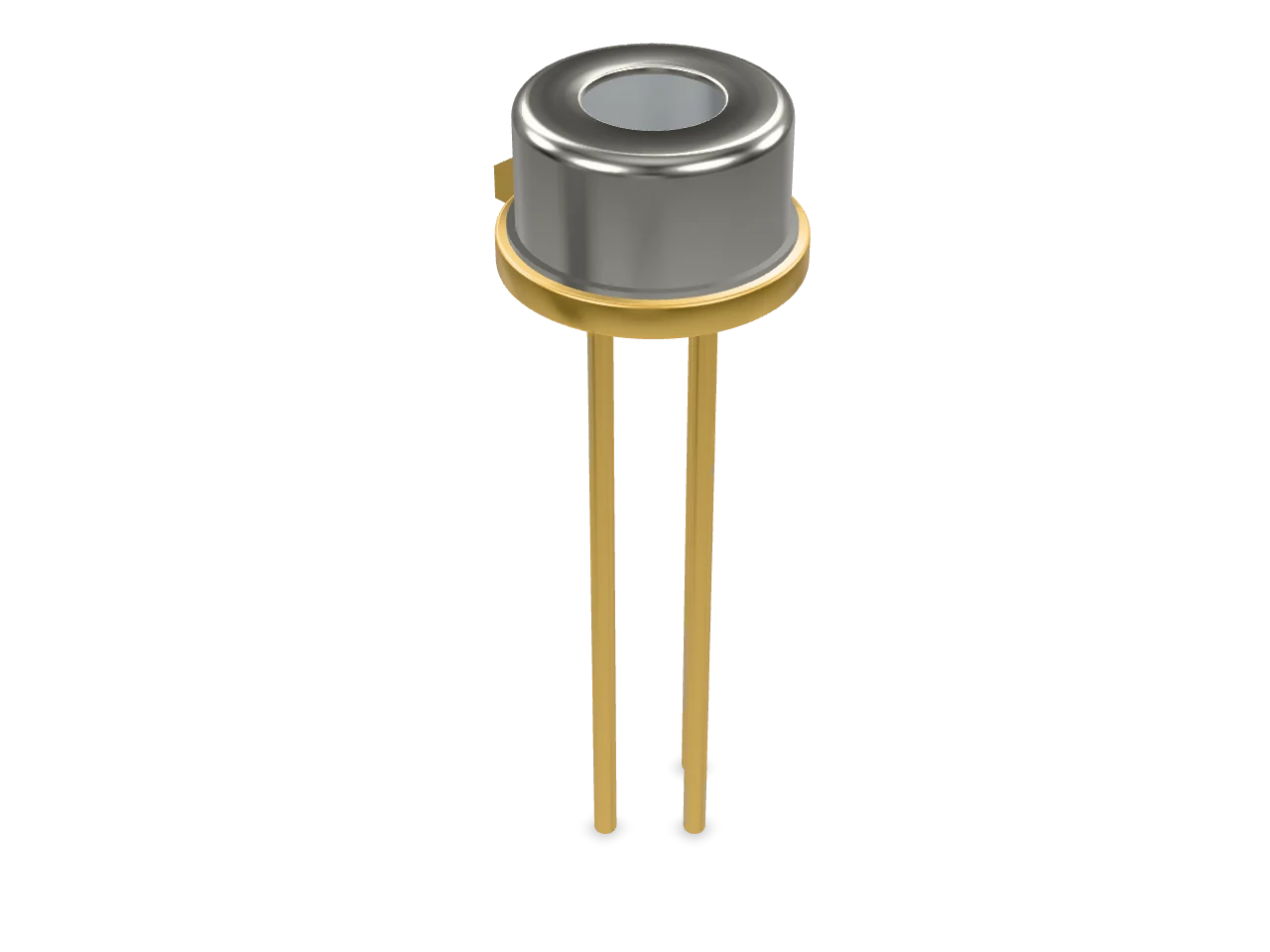
Drag to rotate · pinch to zoom
Illustrative model. A TO-46 style can built to realistic dimensions: a Ø5.40 mm gold-plated header with an orientation tab, a nickel cap with a flat glass window over a Ø1.00 mm active area, and three leads on a Ø2.54 mm circle.
The filter family’s STEP model, outline and mounting drawing and six renders, shown beside its datasheet.
I also do circuit design for photodiode readout electronics: a TIA front end simulated in SPICE and MATLAB, then the KiCad schematic and board.
Shown here for a 14-pin laser diode module: the outline drawing and the KiCad footprint.
This guide covers transmission and blocking requirements through to the specifications for a request for quote. It also serves as the white-paper example, with a selection method and computed worked example.
What’s inside:
Line chart. Wavelength (nm) from 495 to 560. 0°: 0.00 to 0.03; 20°, unpolarized: 0.00 to 0.01; 45°, s: 0.00 to 0.00; 45°, p: 0.06 to 0.02 (Transmission).
The original example has one spec table, no test conditions and a scanned-looking curve. The rewrite adds conditions, limits and computed curves for the filter family.
What changed:
| Wavelength | 532 nm |
| Bandwidth | 3 nm |
| Transmission | >85% |
| Blocking | OD5 |
Specifications subject to change.
| Parameter | Conditions | Min | Typ | Max | Unit |
|---|---|---|---|---|---|
| Center wavelength | AOI 0°, 23 °C | 531 | 532 | 533 | nm |
| Bandwidth (FWHM) | AOI 0° | 2.6 | 3.0 | 3.4 | nm |
| Peak transmission | λ₀, AOI 0° | 85 | 90 | % | |
| Blocking | 400 to 1100 nm | 5 | 6 | OD |
Tolerance notes
For OEM engineers integrating a TEC-cooled laser diode module: from a wavelength tolerance to the sensor, the controller gains and the TEC’s capacity.
What’s inside:
Each example includes its calculation files.
A product-family page for the same filters: hero copy, a spec table with conditions, an eight-question technical FAQ and the inquiry-form questions.
“How far does your filter’s passband move at 10 degrees in an f/2 cone?” About 1,600 words, with two figures drawn from code.
The datasheet, product page and article above, shown as one launch with a short “what shipped when” timeline.
One page for a precision-optics maker: what it makes, three specifications that matter and a design-in checklist.
A synthetic dataset of 24 filter units across temperature: a cleaned workbook, a two-page report with charts from code, and the reusable template.
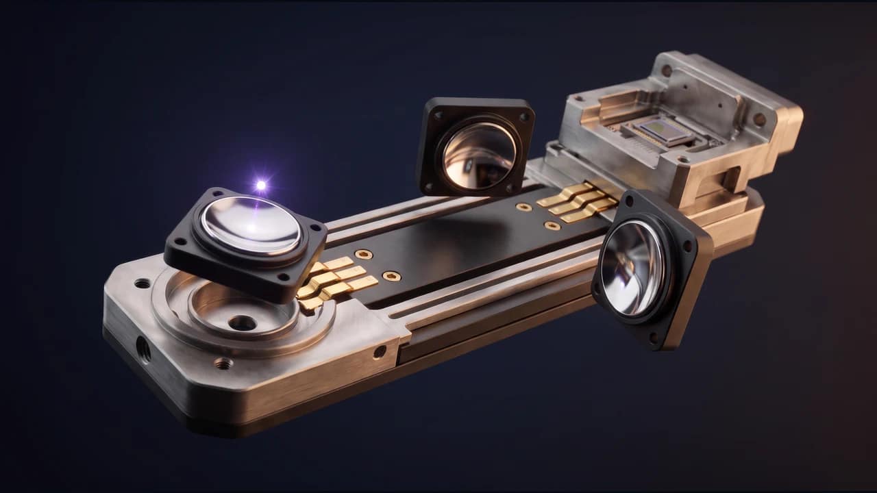
A silent cinematic journey follows EUV light through reflective optics into a silicon photodiode, then follows charge collection through a circuit to a readout signal as the instrument assembles.
Each one runs in your browser. The numbers you enter aren’t sent anywhere.
Enter the drive current, voltage, temperatures and TEC ratings. See the heat load, the TEC current and voltage, and how much of the TEC’s capacity you’re using.
Open the calculatorEnter up to three filters’ optical densities, how much of the blocked light each reflects, and the power you can allow through. See the stack’s OD two ways and whether it blocks enough.
Open the calculatorEnter the center wavelength, effective index and angle, and optionally the f-number of a converging beam. See how far the passband moves, and the tilt that reaches a target wavelength.
Open the calculatorRequest an application note, datasheet refresh or calculator for your parts. You can also start with a free review of your technical content.