Tilting an interference filter moves its passband to shorter wavelengths, and a converging beam applies a range of tilts at once. For a 532 nm filter with a 3.0 nm bandwidth, a 10 degree tilt in collimated light moves the center by −2.009 nm. The same tilt in an f/2 beam moves the average ray’s center by −3.933 nm, spreads the ray centers over 11.15 nm, and turns a flat-topped passband into a lopsided one 7.54 nm wide whose peak transmission falls from 0.90 to 0.39.
The question
Datasheets quote a filter’s center wavelength at normal incidence in a collimated beam. Real instruments rarely provide either: the filter is tilted to keep reflections out of the source or receiver, and the beam is often a cone. How far does the passband move when both happen together?
For a 532 nm line filter with a 3.0 nm bandwidth, tilted 10 degrees in an f/2 beam, the average center moves by about 3.9 nm. That is more than the filter’s whole bandwidth, and it is the smaller problem. The larger one is that the passband stops being a passband at one wavelength. It becomes a smear.
The example is NB-532-3-B: center 532.0 nm, full width at half maximum (FWHM) 3.0 nm, peak transmission 0.90, effective index 2.0, used in air. Every number below is computed from code.
Why tilting moves the passband
An interference filter is a stack of thin layers whose reflections add in phase at the design wavelength. Light arriving at an angle has a shorter optical path between layer surfaces, so the in-phase condition is met at a shorter wavelength. The passband slides toward the blue and never the other way. Lissberger and Wilcock showed that the slide follows a simple law with a single effective index [1]:
Here is the index of the incident medium (1.00 for air) and the angle of incidence. The effective index belongs to the coating design, and a larger value means a smaller shift. It is rarely on a datasheet, but it can be fitted to centers measured at two angles, and Macleod covers its relation to the layers [2]. This article uses 2.0, unpolarized light and one index throughout, and says later when that stops being enough. The range 1.9 to 2.1 changes the f/2 results by about 0.4 nm either way.
Ten degrees in a collimated beam
Put 10 degrees into Eq. (1). The center moves to 529.991 nm, a shift of −2.009 nm, or 0.378 percent of the center wavelength and 0.67 of the bandwidth. A 532 nm laser now sits on the red skirt of the passband, where transmission has fallen from 0.90 to 0.13.
This is why filters for tilted use are ordered long: one made with a center of 534.017 nm sits on 532.000 nm at 10 degrees in collimated light.
What an f/2 cone is
The working f-number is the focal length divided by the aperture diameter, and the cone half angle is . For f/2, is 0.25 and is 14.04 degrees. Each ray meets the filter at its own angle. Tilt the cone axis by 10 degrees and, because 10 is less than 14.04, the cone still straddles the normal: the angles of incidence run from 0 to 24.04 degrees.
Feed those extremes into Eq. (1). The shallowest ray sees a filter centered at 532.000 nm and the steepest sees one centered at 520.850 nm. The ray centers span 11.15 nm, 3.7 times the bandwidth. With no tilt at all, the f/2 cone alone spreads them over 3.93 nm, already wider than the passband.
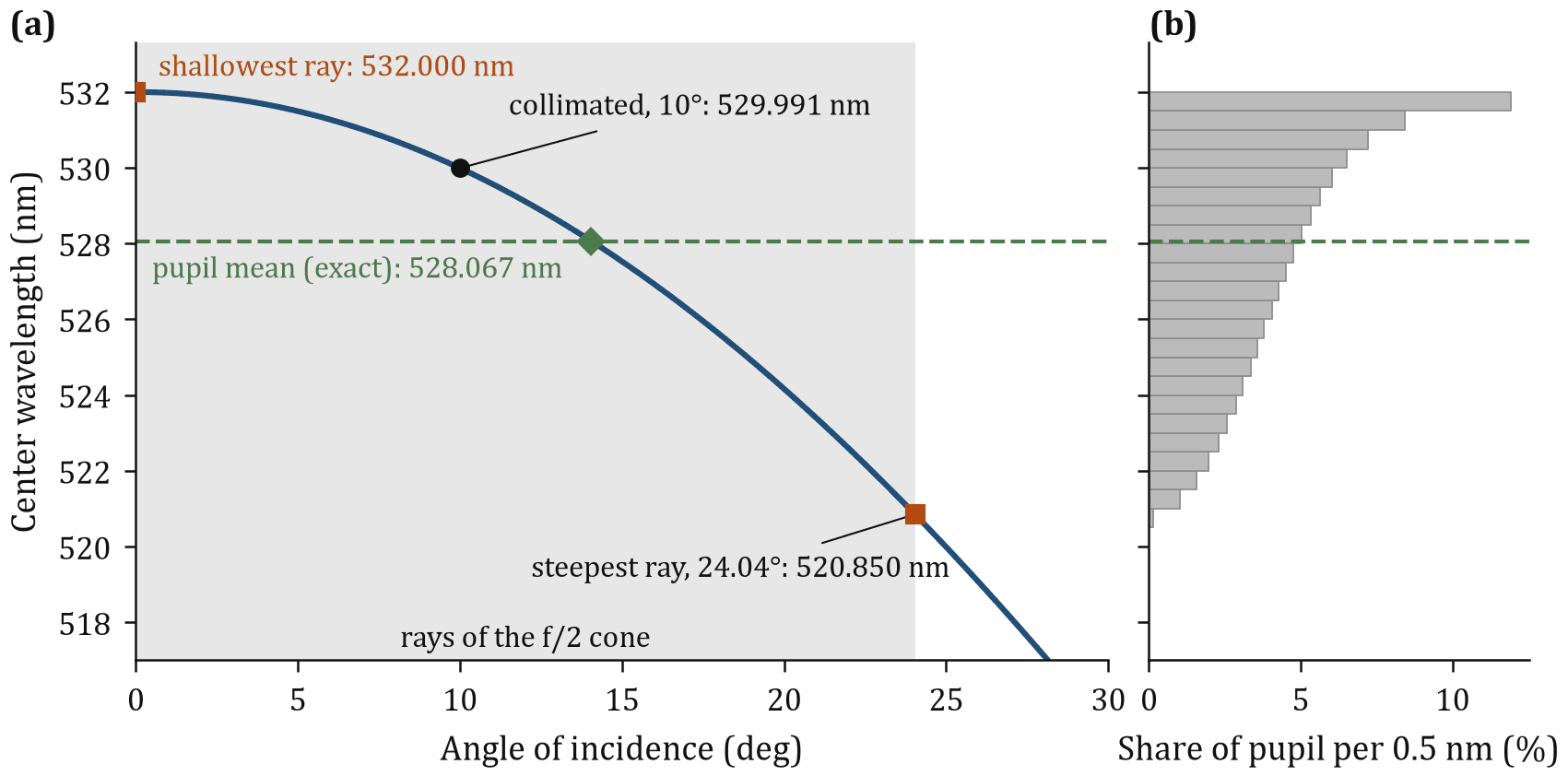
Figure 1b shows the distribution. The curve is flat near normal incidence, so much of the pupil shares nearly the same center and the distribution piles up at the red end.
The average, exact and estimated
The receiver behind the filter adds up all the rays, so the mean center is the single-figure answer. For a uniformly filled circular pupil, averaged over area, the exact mean center is 528.067 nm, a shift of −3.933 nm. It takes numerical integration. The midpoint of the two extreme rays would be 526.425 nm, 1.64 nm off, because most of the pupil lies near the shallow end.
A hand estimate exists. For small angles is about , and the mean of over a uniform disc of half angle is , so
with in radians. For f/2 this gives −1.995 nm. Added to the tilt shift of Eq. (1), it gives −4.004 nm against the exact −3.933 nm. The estimate overstates by 0.071 nm because Eq. (2) assumes a normal axis. A tilted axis scales the cone term by , which is 0.955 at 10 degrees, and with that factor the estimate is −3.914 nm, within 0.019 nm. At zero tilt nothing needs correcting: exact −2.000 nm, estimate −1.995 nm, and both print as −2.00 nm.
From a shift to a smear
A mean shift of −3.9 nm suggests a 3 nm passband parked 4 nm to the blue. It is not. Each ray sees its own passband, centered at its own , and the receiver adds them. If is the passband for center and the share of pupil area with that center (Fig. 1b), the cone transmission is
a convolution of the passband with the distribution of ray centers. Pidgeon and Smith used the effective-index model for filters in nonparallel light [3]. The passband is a flat-topped three-cavity model, , with its width held constant at every angle.
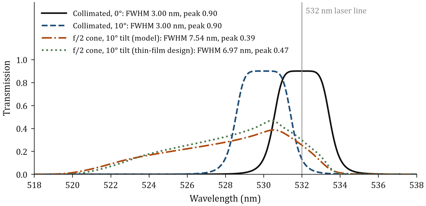
In Fig. 2 the collimated passband at normal incidence is a flat top, FWHM 3.00 nm. At 10 degrees, still collimated, it is the same shape moved by −2.009 nm. In the f/2 cone the flat top is gone: the curve is a lopsided hump, steep on the red side where the near-normal rays pile up and trailing off to the blue. Its half-maximum width is 7.54 nm, 2.5 times nominal, and the peak falls from 0.90 to 0.39, a loss of 57 percent.
The center, as the midpoint of the half-maximum crossings, is 528.697 nm, −3.303 nm from nominal. That is not the −3.933 nm mean ray shift, because a skewed curve is not centered where the average ray is, so a specification of “center wavelength” alone is ambiguous.
A smear keeps the area under the curve. A broadband source that fills the passband still delivers most of its power. A narrow line shows the loss: the 532 nm laser that passed at 0.90 now passes at 0.25. Even at zero tilt the f/2 cone widens the passband to 4.06 nm and cuts the peak to 0.69.
Polarization, and when one index is not enough
The model above is for unpolarized light and a single effective index, the average of the s and p values. At oblique incidence the two polarizations separate: p moves further than s, the p passband widens and the s passband narrows. A transfer-matrix calculation of a representative design quantifies this: a 41-layer three-cavity stack with fitted indices of 2.077 for s and 2.068 for p, average 2.07.
At 10 degrees the s and p centers differ by 0.004 nm, which is nothing. At 24.04 degrees, the steepest ray of the f/2 cone, they differ by 0.144 nm, about a twentieth of the bandwidth, though the widths have drifted apart: 2.72 nm for s and 3.71 nm for p. The average index still predicts the polarization-averaged center to within 0.008 nm. Treating every ray as pure s or pure p, which brackets a polarized source, moves the cone’s center by 0.46 nm and puts its width between 6.50 and 7.42 nm.
The single index stops being good enough when the split reaches a tenth of the bandwidth, 29.5 degrees for this design. At 45 degrees the split is half the bandwidth and the single index is 0.28 nm from the polarization average. Below about 25 degrees it predicts centers to a few hundredths of a nanometer, but widths still change. The dotted curve in Fig. 2 is the thin-film cone result: 6.97 nm wide with a peak of 0.47, against 7.36 nm and 0.47 from the model run with the design’s own index. The model is 0.39 nm wider and 1 percent higher in peak, with centers 0.14 nm apart.
Three remedies
Table 1 puts numbers on the options for a 532 nm laser line. Every filter in it is ordered at the center that puts the half-maximum midpoint on 532.00 nm in its working geometry.
| Case | Ordered center (nm) | FWHM (nm) | Peak | T at 532.00 nm |
|---|---|---|---|---|
| Collimated, 3 nm | 534.02 | 3.00 | 0.90 | 0.90 |
| f/8, 3 nm | 534.11 | 3.22 | 0.86 | 0.86 |
| f/2, 3 nm | 535.32 | 7.57 | 0.38 | 0.30 |
| f/2, 10 nm | 535.57 | 11.43 | 0.80 | 0.80 |
Collimate. At f/8 the half angle is 3.58 degrees and the ray centers span 2.84 nm, so the passband keeps most of its shape. At f/16 the spread is 1.43 nm. If the optical design allows it, put the filter in a collimated section.
Specify wider. At f/2 a 3 nm filter cannot be rescued by ordering long: recentering at 535.32 nm fixes the center but leaves the peak at 0.38. Keeping the peak above 80 percent of 0.90 takes a nominal width of about 7.8 nm, and a 10 nm filter passes the laser at 0.80. The price is more background light.
Order long and tilt. In collimated light this is exact tuning, with full 0.90 transmission on the line. In a cone it recenters the passband but cannot restore the peak.
What to ask the supplier
Ask for the effective index of your coating, its polarization and how it was measured. Ask for measured curves at normal incidence and at your working angle. Ask for the f-number of the beam behind the specifications, since most datasheets quote a collimated beam a few millimeters wide. A center tolerance of ±1 nm means little if the cone alone moves it by 3.9 nm.
Limits of this calculation
The cone is a uniformly filled disc in air; a Gaussian beam smears somewhat less. Confirm the final choice against measured curves at your angles.
The angle shift calculator takes center wavelength, effective index, angle and f-number and returns the tilt shift, the edge rays and the cone term used here. The optical filter selection guide covers where angle sits beside bandwidth, blocking and substrate.
Symbols: center wavelength at normal incidence; angle of incidence; index of the incident medium; effective index of the coating; working f-number; cone half angle; FWHM full width at half maximum.
Basis: every derived number is computed in Python and checked against the stored results by an automated audit before the article is rendered, and an independent MATLAB implementation reproduces them. The exact pupil average uses polar quadrature over a uniformly filled circular pupil. The thin-film check is a transfer-matrix calculation of a representative design with non-dispersive indices (2.30 and 1.46) on a 1.46 substrate, transmittance into the substrate.
NB-532-3-B is a fictional filter, and Sespe Optics is a fictional company.
References
- [1]P. H. Lissberger and W. L. Wilcock, “Properties of all-dielectric interference filters. II. Filters in parallel beams of light incident obliquely and in convergent beams,” J. Opt. Soc. Am. 49, 126-130 (1959), doi:10.1364/JOSA.49.000126.
- [2]H. A. Macleod, Thin-Film Optical Filters, 5th ed., CRC Press, 2017, ISBN 978-1138198241.
- [3]C. R. Pidgeon and S. D. Smith, “Resolving power of multilayer filters in nonparallel light,” J. Opt. Soc. Am. 54, 1459-1466 (1964), doi:10.1364/JOSA.54.001459.